


SERVICIOS INTEGRADOS PARA MÚSICOS
Producción, grabación, mezcla y masterización de tu álbum o single de una manera cercana y siempre priorizando la calidad musical de tu trabajo.
Fotografía, video, gestión de redes sociales y organización de presentaciones en directo de tu trabajo discográfico.
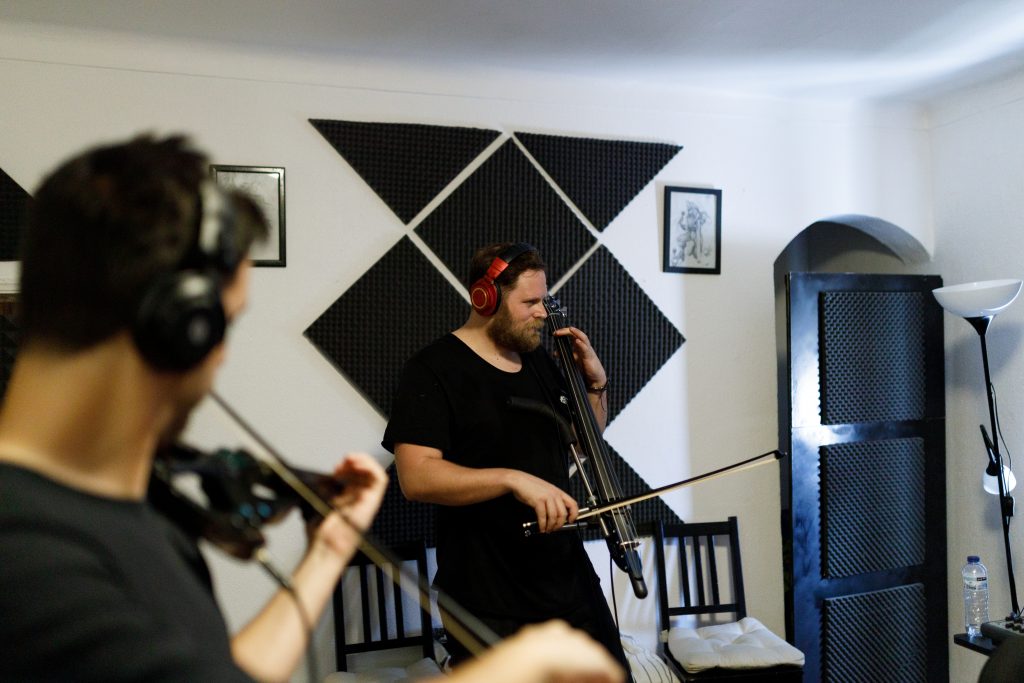
CUARTETO DE CUERDAS
Agrupación musical para todo tipo de eventos, con un amplio repertorio musical, desde clásico, jazz, versiones de rock, bandas sonoras, música celta, etc.
Preparado para tocar en bodas, bautizos, comuniones, cockteles, comidas, y eventos empresariales de cualquier género.
ARREGLOS Y ORQUESTACIONES
Arreglos en partituras y en pistas “midi” de cualquier tema que quieras para la formación solicitada.
No te olvides de preguntar por nuestros packs de arreglos para cuarteto de cuerdas, grabación de cuerdas y presentaciones en directo acompañado de nuestro cuarteto de cuerdas “Busker String Quartet”.
PROFESIONALIDAD
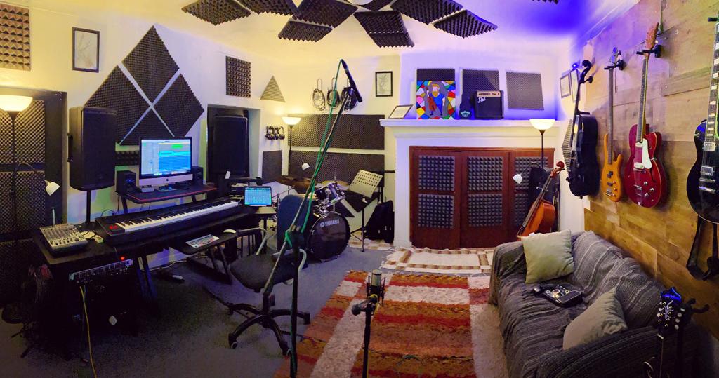
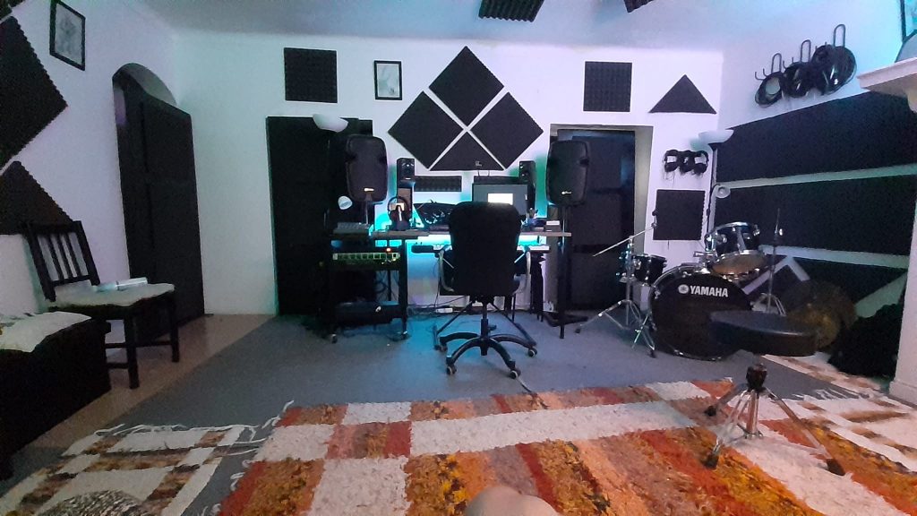
Nuestra editora trabaja la producción musical de una manera enfocada en priorizar la formación y un resultado musical del más alto nivel. Contamos con músicos y técnicos con una amplia experiencia en producción de trabajos discográficos de éxito internacional
Red Maple Records surge para gestionar un espacio musical poco explorado en la zona de la raya extremeña-alentejana. Especializándose en proyectos de caracter semiacústicos y alternativos como es el folk tradicional, clásico o el rock alternativo.
Entre sus trabajos principales destaca el álbum “Bridgit & Gwydion Trilogy” del cuarteto de cuerdas pacense “Busker String Quartet” lanzado en 2016 el cual cosiguió presentaciones a nivel nacional en España y Portugal conquistando el mercado extremeño y “Ciorcal Suite” lanzado en 2019 el cual lanzó el cuarteto al panorama nacional.
Disfruta también de nuestro magnífico ambiente de trabajo y de la participación en lo que será nuestro futuro festival de grupos de nuestra casa, el “RED MAPLE FEST”

Arreglos para cuarteto de cuerdas de todo tipo de canciones, desde bandas sonoras, rock, pop, anime, etc.
Tienda de partituras
Tienda de Partituras
-
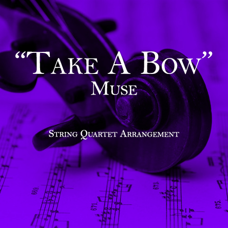 Take A Bow – Muse – String Quartet Arrangement15,00 €
 -
 Supermassive Black Hole – Muse – String Quartet Arrangement15,00 €
 -
 The Streets Of Whiterun – Skyrim – String Quartet Arrangement15,00 €
 -
 From Past to Present- Skyrim – String Quartet Arrangement15,00 €
 -
 Pirates of The Caribbean – Original Soundtrack – String Quartet Arrangement15,00 €
 -
 My Way – Jacques Revaux – String Quartet10,00 €
 -
 Moon River – H. Mancini – String Quartet Arrangement10,00 €
 -
 Map Of The Problematic – Muse – String Quartet Arrangement15,00 €
 -
 Lovely – Billie Eilish – String Quartet Arrangement15,00 €


